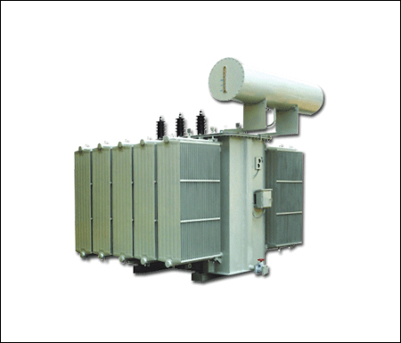
Distribution Transformer
Application
Distribution Transformer is an electrical isolation transformer which converts high-voltage electricity to lower voltage levels acceptable for use in homes and business. A distribution transformer’s function is straightforward: to step down the voltage and provide isolation between primary and secondary. Electrical energy is passed through distribution transformers to reduce high-distribution voltage levels down to end-use levels. Nearly all energy passes through at least one distribution transformer before being consumed by an end-use appliance, motor, or other piece of equipment. Distribution Transformers are found in all sectors of the economy: residential, commercial, and industrial.
Distribution transformers are generally categorized in several ways:
type of insulation: liquid-immersed or dry-type
number of phases: single-phase or three-phase
voltage level (for dry-type): low or medium
General purpose distribution Transformers
A distribution transformer or service transformer is a transformer that provides the final voltage transformation in the electric power distribution system, stepping down the voltage used in the distribution lines to the level used by the customer, these are generally used for supply appliance, lighting, motorized machine and power loads from electrical distribution systems.
Distribution Transformers provide the necessary power for systems and buildings on the last transformation step from the power station to the consumer. Accordingly, their operation must be reliable, efficient and at the same time silent.
They are either ventilated or totally enclosed, and are available with either aluminum or copper windings in standard ratings from 50KVA up to 3000kVA and more. The final part of the distribution system at medium voltage is the distribution transformers
Construction
Distribution transformers are made using a core made from laminations of sheet steel stacked and either glued together with resin or banded together with steel straps. Where large numbers of transformers are made to standard designs, a wound C-shaped core is economic to manufacture. A steel strip is wrapped around a former, pressed into shape and then cut into two C-shaped halves, which are re-assembled on the copper windings.
The primary coils are wound from enamel coated copper or aluminum wire and the high current, low voltage secondary are wound using a thick ribbon of aluminum or copper. The windings are insulated with resin-impregnated paper. The entire assembly is baked to cure the resin and then submerged in a powder coated steel tank which is then filled with transformer oil (or other insulating liquid), which is inert and non-conductive. The transformer oil cools and insulates the windings, and protects the transformer winding from moisture, which will float on the surface of the oil. The tank is temporarily depressurized to remove any remaining moisture that would cause arcing and is sealed against the weather with a gasket at the top.
Formerly, distribution transformers for indoor use would be filled with a polychlorinated biphenyl (PCB) liquid. Because these liquids persist in the environment and have adverse effects on animals, they have been banned. Other fire-resistant liquids such as silicones are used where a liquid-filled transformer must be used indoors. Certain vegetable oils have been applied as transformer oil; these have the advantage of a high fire point and are completely biodegradable in the environment
Pole-mounted transformers often include accessories such as surge arresters or protective fuse links. A self-protected transformer includes an internal fuse and surge arrester; other transformers have these components mounted separately outside the tank. Pole-mounted transformers may have lugs allowing direct mounting to a pole, or may be mounted on cross arms bolted to the pole. Aerial transformers, larger than around 75kVA, may be mounted on a platform supported by one or more poles. A three-phase service may use three identical transformers, one per phase.
Transformers designed for below-grade installation can be designed for periodic submersion in water Distribution transformers may include an off-load tap changer to allow slight adjustment of the ratio between primary and secondary voltage, to bring the customer voltage within the desired range on long or heavily loaded lines. Pad-mounted transformers have secure locked and bolted grounded metal enclosures to discourage unauthorized access to live internal parts. The enclosure may also include fuses, isolating switches, load-break bushings, and other accessories as described in technical standards. Pad-mounted transformers for distribution systems typically range from around 5kVA to 3000 kVA and more, although some larger units are also used
| Rated PowerkVA | No loadLoss (Watt) | Load Loss | Imped. Volt | Regulation | Regulation | Efficiency at P.f=1 | ||
| At 75°C (Watt) | At 75°C (Watt) | At p.f=1 | At p.f=0.8 | At load 100% | At Load 75% | At load 50% | ||
| 100KVA | 300 | 1750 | 4 | 1.94 | 4.15 | 97.74 | 98.20 | 98.46 |
| 150KVA | 350 | 2600 | 4 | 1.68 | 3.98 | 98.30 | 98.75 | 99.10 |
| 200KVA | 500 | 2850 | 4 | 1.50 | 3.88 | 98.20 | 98.52 | 98.95 |
| 250KVA | 600 | 3250 | 4 | 1.36 | 3.75 | 98.25 | 98.69 | 99.10 |
| 315KVA | 800 | 4500 | 4 | 1.29 | 3.75 | 98.20 | 98.50 | 98.95 |
| 400KVA | 1000 | 5000 | 4 | 1.23 | 3.72 | 98.10 | 98.52 | 98.94 |
| 500KVA | 1150 | 5500 | 4 | 1.16 | 3.65 | 98.32 | 98.62 | 99.00 |
| 630KVA | 1500 | 6500 | 4 | 1.10 | 3.60 | 98.52 | 98.96 | 99.10 |
| 750KVA | 1850 | 8500 | 5 | 1.15 | 3.60 | 98.62 | 99.10 | 99.25 |
| 800KVA | 2000 | 9000 | 5 | 1.20 | 4.00 | 98.75 | 99.00 | 99.25 |
| 1000KVA | 2500 | 12000 | 5 | 1.25 | 4.20 | 98.50 | 98.85 | 99.20 |
| 1250KVA | 2850 | 13500 | 6.5 | 1.15 | 4.25 | 98.30 | 99.00 | 99.15 |
| 1500KVA | 3250 | 16500 | 6.5 | 1.15 | 4.10 | 98.25 | 98.85 | 99.16 |
| 2000KVA | 4000 | 20000 | 6.5 | 1.15 | 4.15 | 98.40 | 98.75 | 99.15 |
| 2500KVA | 4500 | 25000 | 6.5 | 1.15 | 4.20 | 98.35 | 98.99 | 99.17 |
| 3000KVA | 5000 | 32000 | 6.5 | 1.15 | 4.10 | 98.50 | 98.95 | 99.15 |
Note: The given results are average value of different time production, it’s not a constant value, can be minor changed at the time of production